 |
||||||||||||||||||||||||||||||||||||||||||||||||||||||||||||||||||||||||||||||||||||||||||||||||||||||||||||||||||||||||||||||||||||||||||||||||||||||||||||||||||||||||||||||||||||||||||||||||||||||||||||||||||||||||||||||||||||||||||||||||||||||||||||||||||||||||||||||||||||||||||||||||||||||||||||||||||||||||||||||||||||||||||||||||||||||||||||||||||||||||||||||||||||||||||||||||||||||||||||||||||||||||||||||||||||||||||||||||||||||
|
astronomy notes - Newtonian Telescope |
||||||||||||||||||||||||||||||||||||||||||||||||||||||||||||||||||||||||||||||||||||||||||||||||||||||||||||||||||||||||||||||||||||||||||||||||||||||||||||||||||||||||||||||||||||||||||||||||||||||||||||||||||||||||||||||||||||||||||||||||||||||||||||||||||||||||||||||||||||||||||||||||||||||||||||||||||||||||||||||||||||||||||||||||||||||||||||||||||||||||||||||||||||||||||||||||||||||||||||||||||||||||||||||||||||||||||||||||||||||
|
Focal Length, call it f, is the distance from the mirror where the light from a very distant object (effectively at infinity) comes to a focus. D is the diameter of the primary mirror. Figure 1.
Note that the light comes to a focus in the path of the incoming light. One has to either put a detector there or redirect the light somewhere else. Common options are to cut a hole in the mirror and reflect the light to the back of the telescope, or redirect it to the side. The latter is called a Newtonian design, and it's what we'll do. Figure 2.
The first question is how big of a flat secondary mirror we need. The flat doesn't change the convergence of light, just redirects it. Thus the total distance of focus, the focal length, is the same. If we redirect the light a distance 'a' before the original focal point, what is the diameter of the flat mirror, 'd'? Figure 3.
If the flat were put right in front of the primary (a = f), then it would have to be as big as the primary (d = D). If we put the flat at the focal point (a = 0), then theoretically it wouldn't have to be any size at all, since it is at a point (d = 0). By symmetry, the size should scale with the distance from the mirror. The relationship which accomplishes all of these is
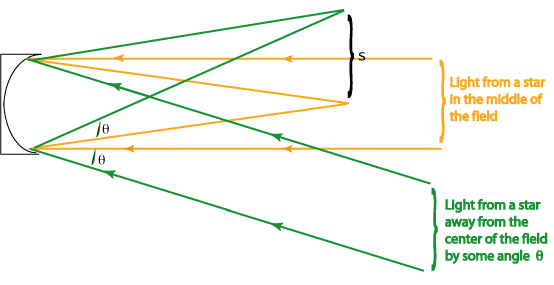
The ratio of focal length to diameter comes up so often in optics that it's given a special name, "f-number," and is often abbreviated "f/#." This isn't a division; it's not f divided by #. Rather, it's a single symbol that's in common usage. You'll see it on SLR camera lenses, often giving specific numbers. For more info on SLR cameras try the Nikon site http://www.nikon.co.jp/main/eng/photo_world/kumon/index.htm. The mirrors we will use are f/6.7. This means the focal length is 6.7 times the diameter. The diameters we chose are 150 mm, so that means the focal lengths are ~ 1005 mm. If you look at the sketches above, you can also see that the f/# tells you how tightly the light beam converges. A low f/# means that the light comes to focus in a relatively short distance. This is often called "fast," as in a "fast mirror," or "a fast beam." A larger f/# is called "slower." Getting back to our little formula for the size of the flat secondary, we can rewrite it as We're not done yet, however. If you look at the schematic above, you'll see that we only considered light rays that were coming in parallel to the tube and the optical axis (line through the center of the system, perpendicular to the mirror). These rays come from a point right at the center of the field we're looking at, such as a star right in the center of the field of view. We want to look at more than one start. So what happens to our calculation of d is we consider the field of view? Does d get larger or smaller? To get to this, we have to consider what happens to light rays from sources that are off center. To simplifiy the problem, just consider the primary mirror, ignoring for the moment the tube and the flat secondary. Figure 4 (Not to scale. In particular, the offset is exaggerated hugely.)
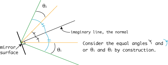
Even though I haven't drawn it well, the two angles labeled by Figure 5.
So, for some angle
Let's plug some numbers in. A typical field of view for a telescope is around half a degree to a degree. Let's start with 0.5 degrees. Remember, that's the full field, on both sides of the center, so set
That means the distance in the focal plane corresponding to the quarter degree, divided by the focal length is this number:
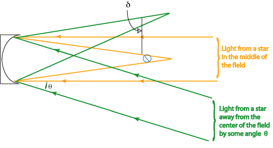
For our mirror, the focal length is about 100.5 mm, which means s = 4.39 mm. Since this was for half of the field of view, double it to get that a 0.5 degree field maps onto an area of about 8.77 mm across at the focus. That's how big your film, or electronic detector, has to be if you want to take a picture. More importantly, for our purposes, that's how big a patch the eyepiece has to see if we want to look at the whole field. Now we can go back to the first issue of how much bigger the secondary flat has to be to accomodate the field of view we want. Let's start with a similar drawing to the last one. Figure 6 (Not to scale. In particular, the offset is exaggerated hugely.)
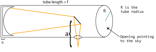
We can figure This is the same relation as the formula given in the online telescope building instructions, http://members.aol.com/sfsidewalk/sources.htm, about 1/4 of the way down. However, at first it doesn't look like it because theyuse different symbols and have them arranged differently. Symbol substitution and algebraic manipulation makes them equivalent. This is an important lesson and algebra skill because one often finds a great range of symbols representing the same thing, sometimes even in the same book or article. Also, formulas can be presented in different ways which are algebraically equivalent. Let's plug in some numbers and see how big of a flat to get. We already know the focal length, f, and the f/#. We know what a typical f.o.v. is. What about a? You can tell from looking at Figure 2 that is has to be about the radius of the tube. In practice, it's a little longer since it has to be in the right position for the eyepiece. There's a pretty good explanation of this in the online instructions, http://members.aol.com/sfsidewalk/sectiona.htm, about 1/2 way down. The rule of thumb is to cut the tube to be the same length as the focal length of the mirror. The drill a hole in the side of the tube back from the end by an amount equal to the radius. Figure 7.
The face of the mirror isn't right at the back of the tube because it has some thickness plus there is some mounting hardware. The net result is that the surface is offset from the back by an amount b, which is typically about 2 inches for the mirrors we'll use. So the light travels a distance in the tube which is the tube length - R - b. The distance after the flat is a and the total distance to the focal point is the focal length f.
Since we cut the tube to have the length = f, f = (f - R - b) + a So the distance after the flat is approximately the tube radius + the amount by which the mirror surface is beyond the back of the tube. See the website for more diagrams and discussion. We'll use 8" diameter tubes, and for the mirror offset from the back by 2", a = 6" = 152 mm. That's the last piece we need to calculate the size of the secondary flat mirror. Plug it in to get d' = 30.1 mm which is about 1.19 inches. 1.18 inches is one of the standard sizes for flat secondary mirrors (see, for example, http://www.telescope.com and search on "mirror"). Are these designed just for our setup (6" f/6.7 mirror; 8" tube) or would these work with an 8" mirror, 10" tube and one of the standard f/#s?
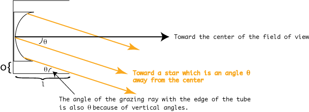
Unfortunately, one of the large vendors is out of the 1.18" flats, so we're considering going to the next larger size of 1.36". If you plug in that for d' and solve for f.o.v., then you get 0.8 degrees. Are we done worrying about field of view and sizes of flats? Not quite. Look back at Figure 4. You'll notice I conveniently didn't draw the tube. Wouldn't some of the light rays hit the side of the tube? If the mirror were as big as the tube, definitely yes. Blocking some of the incoming light rays like this is called vignetting. One of the reasons we buy tubes that are bigger than the mirrors, is to avoid, or at least reduce, this problem. Let's make another diagram of the mirror and tube, this time with a really short tube to exaggerate the effect so we can see it. Figure 8.
The diagram is set up so that one of the rays just barely misses the top of the tube. If the angle were any larger, some of the light would be blocked. What is this maximum unvignetted angle? Well, simple trig says
If the kids haven;t gotten to trig yet, this can be stewed down to tan
Plugging in numbers.... We'll use a 6" mirror and an 8" tube, so o = 1" = 25 mm. l will be about the focal length (remember, tube is cut to that length) minus the offset of the mirror from the back, which we said wa about 2" (51 mm). So, l = 1005 mm - 51 mm = 954 mm.
remember, A neat calculus exercise would be to derive the amount of light lost as a function of
|
|||||||||||||||||||||||||||||||||||||||||||||||||||||||||||||||||||||||||||||||||||||||||||||||||||||||||||||||||||||||||||||||||||||||||||||||||||||||||||||||||||||||||||||||||||||||||||||||||||||||||||||||||||||||||||||||||||||||||||||||||||||||||||||||||||||||||||||||||||||||||||||||||||||||||||||||||||||||||||||||||||||||||||||||||||||||||||||||||||||||||||||||||||||||||||||||||||||||||||||||||||||||||||||||||||||||||||||||||||||
|
home | field activities | semester project | course information |
||||||||||||||||||||||||||||||||||||||||||||||||||||||||||||||||||||||||||||||||||||||||||||||||||||||||||||||||||||||||||||||||||||||||||||||||||||||||||||||||||||||||||||||||||||||||||||||||||||||||||||||||||||||||||||||||||||||||||||||||||||||||||||||||||||||||||||||||||||||||||||||||||||||||||||||||||||||||||||||||||||||||||||||||||||||||||||||||||||||||||||||||||||||||||||||||||||||||||||||||||||||||||||||||||||||||||||||||||||||


